IPsec VTI - Route based setup
Most Site-to-Site VPNs are policy-based, which means you define a local and a remote network (or group of networks). Only traffic matching the defined policy is pushed into the VPN tunnel. As the demands for more complex and fault tolerant VPN scenarios have grown over the years, most major router vendors implemented a kind of VPN, the route-based IPSec.
The difference is that local and remote network is just 0.0.0.0/0, so anything can travel through the tunnel, it just needs a route. A new Virtual Tunnel Interface (VTI) has to be used for this.
There are two benefits for this kind of VPN:
First, you can set up two tunnels to the same gateway and failover when one line goes down. Second, you can run dynamic routing protocols over the tunnel to create more redundant, or software-defined networks.
Note
For a stable setup, we highly advise using standard IPv4 / IPv6 addresses, although the web interface allows the use of fully qualified domain names (e.g. my.own.domain.xyz), this will have side affects (the tunnel device won’t react on name changes for example).
Before you start
Before starting with the configuration of an IPsec tunnel you need to have a working OPNsense installation with a unique LAN IP subnet for each side of your connection (your local network needs a different one than the remote network).
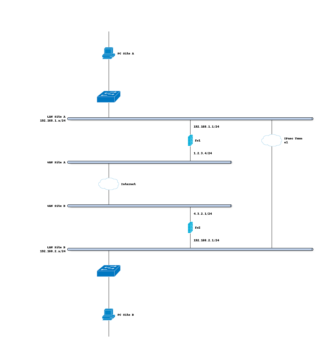
Sample Setup
For the sample configuration we use two OPNsense boxes to simulate a site to site tunnel, with the following configuration:
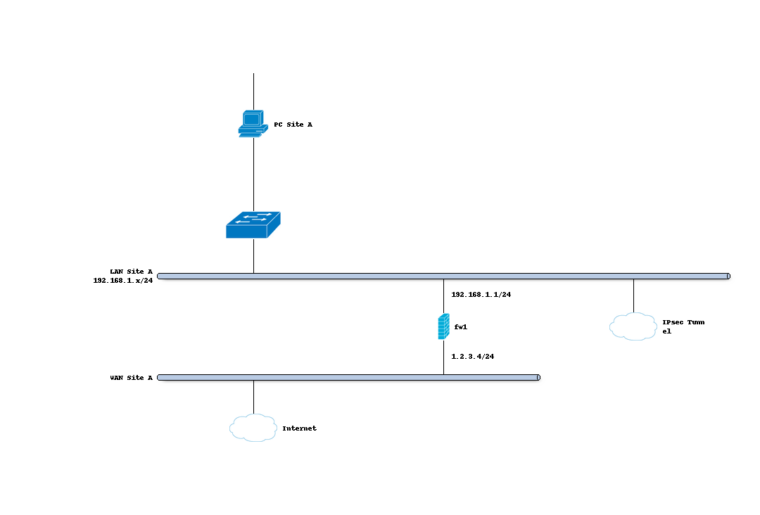
Site A
Hostname |
fw1 |
WAN IP |
1.2.3.4/24 |
LAN IP |
192.168.1.1/24 |
LAN DHCP Range |
192.168.1.100-192.168.1.200 |

Site B
Hostname |
fw2 |
WAN IP |
4.3.2.1/24 |
LAN Net |
192.168.2.0/24 |
LAN DHCP Range |
192.168.2.100-192.168.2.200 |
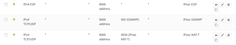
Firewall Rules Site A & Site B (part 1)
To allow IPsec tunnel connections, the following should be allowed on WAN for on sites (under ):
Protocol ESP
UDP Traffic on port 500 (ISAKMP)
UDP Traffic on port 4500 (NAT-T)
Note
You can further limit the traffic by the source IP of the remote host.
Step 1 - Phase 1 Site A
(Under Press +) We will use the following settings:
General information
Connection method |
default |
Default is “Start on traffic” |
Key Exchange version |
V2 |
|
Internet Protocol |
IPv4 |
|
Interface |
WAN |
Choose the interface connected to the internet |
Remote gateway |
4.3.2.1 |
The public IP address of your remote OPNsense |
Description |
Site B |
Freely chosen description |
Phase 1 proposal (Authentication)
Authentication method |
Mutual PSK |
Using a Pre-shared Key |
My identifier |
My IP address |
Simple identification for fixed IP |
Peer identifier |
Peer IP address |
Simple identification for fixed IP |
Pre-Shared Key |
At4aDMOAOub2NwT6gMHA |
Random key. CREATE YOUR OWN! |
Phase 1 proposal (Algorithms)
Encryption algorithm |
AES |
For our sample we will use AES/256 bits |
Hash algorithm |
SHA512 |
Use a strong hash like SHA512 |
DH key group |
14 (2048 bit) |
2048 bit should be sufficient |
Lifetime |
28800 sec |
Lifetime before renegotiation |
Advanced Options
Install Policy |
Unchecked |
This has to be unchecked since we want plain routing |
Disable Rekey |
Unchecked |
Renegotiate when connection is about to expire |
Disable Reauth |
Unchecked |
For IKEv2 only re-authenticate peer on rekeying |
NAT Traversal |
Disabled |
For IKEv2 NAT traversal is always enabled |
Dead Peer Detection |
Unchecked |
Save your setting by pressing:

Step 2 - Phase 2 Site A
Press the button + in front of the phase 1 entry to add a new phase 2.
As we do not define a local and remote network, we just use tunnel addresses,
you might already know from OpenVPN. In this example we use 10.111.1.1 and
10.111.1.2. These will be the gateway addresses used for routing
General information
Mode |
Route-based |
Select Route-based |
Description |
Local LAN Site B |
Freely chosen description |
Tunnel Network
Local Address |
Local Tunnel IP |
Set IP 10.111.1.1 |
Remote Address |
Remote Tunnel IP |
Set IP 10.111.1.2 |
Phase 2 proposal (SA/Key Exchange)
Protocol |
ESP |
Choose ESP for encryption |
Encryption algorithms |
AES / 256 |
For the sample we use AES 256 |
Hash algorithms |
SHA512 |
Choose a strong hash like SHA512 |
PFS Key group |
14 (2048 bit) |
Not required but enhanced security |
Lifetime |
3600 sec |
Save your settings by pressing:
Enable IPsec for Site A, select:
Save:
And apply changes:


You are almost done configuring Site A (only some firewall settings remain, which will be addressed later). We will now proceed setting up Site B.
Step 3 - Phase 1 Site B
(Under Press +) We will use the following settings:
General information
Connection method |
Default |
Default is ‘Start on traffic’ |
Key Exchange version |
V2 |
|
Internet Protocol |
IPv4 |
|
Interface |
WAN |
Choose the interface connected to the internet |
Remote gateway |
1.2.3.4 |
The public IP address of your remote OPNsense |
Description |
Site A |
Freely chosen description |
Phase 1 proposal (Authentication)
Authentication method |
Mutual PSK |
Using a Pre-shared Key |
My identifier |
My IP address |
Simple identification for fixed ip |
Peer identifier |
Peer IP address |
Simple identification for fixed ip |
Pre-Shared Key |
At4aDMOAOub2NwT6gMHA |
Random key. CREATE YOUR OWN! |
Phase 1 proposal (Algorithms)
Encryption algorithm |
AES |
For our sample we will use AES/256 bits |
Hash algorithm |
SHA512 |
Use a strong hash like SHA512 |
DH key group |
14 (2048 bit) |
2048 bit should be sufficient |
Lifetime |
28800 sec |
Lifetime before renegotiation |
Advanced Options
Install Policy |
Unchecked |
This has to be unchecked since we want plain routing |
Disable Rekey |
Unchecked |
Renegotiate when connection is about to expire |
Disable Reauth |
Unchecked |
For IKEv2 only re-authenticate peer on rekeying |
NAT Traversal |
Disabled |
For IKEv2 NAT traversal is always enabled |
Dead Peer Detection |
Unchecked |
Save your setting by pressing:
Step 4 - Phase 2 Site B
Press the button + in front of the phase 1 entry to add a new phase 2.
General information
Mode |
Route-based |
Select Route-based |
Description |
Local LAN Site A |
Freely chosen description |
Tunnel Network
Local Address |
Local Tunnel IP |
Set IP 10.111.1.2 |
Remote Address |
Remote Tunnel IP |
Set IP 10.111.1.1 |
Phase 2 proposal (SA/Key Exchange)
Protocol |
ESP |
Choose ESP for encryption |
Encryption algorithms |
AES / 256 |
For the sample we use AES 256 |
Hash algorithms |
SHA512 |
Choose a strong hash like SHA512 |
PFS Key group |
14 (2048 bit) |
Not required but enhanced security |
Lifetime |
3600 sec |
Save your setting by pressing:
Enable IPsec for Site B, Select:
Save:
And apply changes:
Firewall Rules Site A & Site B (part 2)
To allow traffic passing to your LAN subnet you need to add a rule to the IPsec interface (under ).

IPsec Tunnel Ready
The tunnel should now be up and routing the both networks. Go to to see current status.
Step 5 - Define Gateways
Now that you have the VPN up and running you have to set up a gateway. Go to and add a new gateway.
Gateway Site-A
Name |
VPNGW |
Set a name for your gateway |
Interface |
IPSEC1000 |
Choose the IPsec interface |
IP Address |
10.111.1.2 |
Set the peer IP address |
Far Gateway |
Checked |
This has to be checked as it is a point-to-point connection |
Gateway Site-B
Name |
VPNGW |
Set a name for your gateway |
Interface |
IPSEC1000 |
Choose the IPsec interface |
IP Address |
10.111.1.1 |
Set the peer IP address |
Far Gateway |
checked |
This has to be checked as it is a point-to-point connection |
Step 5 - Add Static Routes
When gateways are set up you can add a route for the remote network pointing to the new gateway. On Site-A add a route to Site-B and vice versa. Go to .
Route Site-A
Network Address |
192.168.2.0/24 |
Set the network of Site-B |
Gateway |
VPNGW |
Select the VPN gateway |
Gateway Site-B
Network Address |
192.168.1.0/24 |
Set the network of Site-A |
Gateway |
VPNGW |
Select the VPN gateway |
Now you are all set!