Configure CARP
Overview
One of the more powerful features of OPNsense is to set-up a redundant firewall with automatic fail-over option. This chapter describes step by step how to create a set-up based on two networks. The 192.168.1.0/24 will be used for the internal network and 172.18.0.0/24 will be used to route our traffic to the internet.
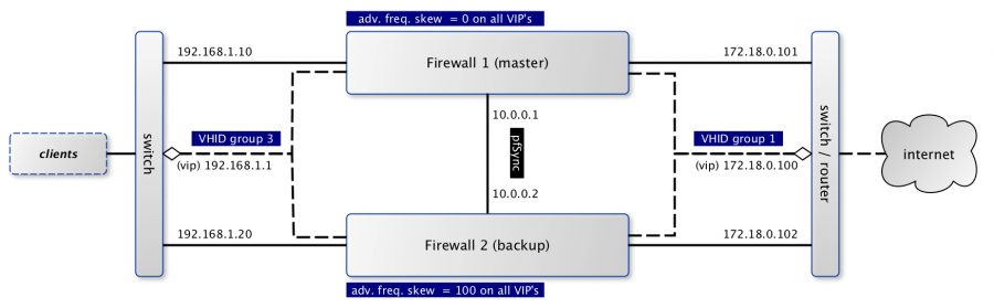
When using CARP ( FreeBSD handbook on CARP ), all fail-safe interfaces should have a dedicated IP address which will be combined with one shared virtual IP address to communicate to both networks. In the picture above the dashed lines are used to mark the virtual addresses.
The configuration file (XML) for both firewalls can be downloaded from the wiki.
Terminology
There is some terminology involved in setting up a CARP cluster, which we will explain briefly first:
CARP
Common Address Redundancy Protocol uses IP protocol 112, is derived from OpenBSD and uses multicast packets to signal its neighbours about its status. Always make sure that each interface can receive CARP packets. Every virtual interface must have a unique Virtual Host ID (vhid), which is shared across the physical machines. To determine which physical machine has a higher priority, the advertised skew is used. A lower skew means a higher score. (our master firewall uses 0).
pfSync
Together with CARP, we can use pfSync to replicate our firewalls state. When failing over you need to make sure both machines know about all connections to make the migration seamless. It’s highly advisable to use a dedicated interface for pfSync packets between the hosts, both for security reasons (state injection) as for performance.
Warning
When using different network drivers on both machines, like running a HA setup with one physical machine as master and a virtual machine as slave, states can not be synced as interface names differ. The only workaround would be to set up a LAGG.
XMLRPC sync
OPNsense includes a mechanism to keep the configuration of the backup server in sync with the master. This mechanism is called XMLRPC sync and can be found under .
Configuring CARP for IPv4
Setup interfaces & basic firewall rules
Warning
Make sure the interface assignments on both systems are identical! Via you can check if e.g. DMZ is opt1 on both machines. When the assignments differ you will have mixed Master and Backup IPs on both machines.
Our example uses three interfaces, which all have a rather basic setup.
Master
Go to interfaces, make sure you have all three interfaces assigned and setup the following addresses and subnets:
LAN 192.168.1.10/24 |
WAN 172.18.0.101/24 |
PFSYNC 10.0.0.1 |
Next we need to make sure the appropriate protocols can be used on the different interfaces, go to and make sure both LAN and WAN accept at least CARP packets (see protocol selection). Because we’re connecting both firewalls using a direct cable connection, we will add a single rule to accept all traffic on all protocols for that specific interface. Another option is to only accept traffic to the GUI port and pfSync protocol.
Backup
The backup server needs its own dedicated addresses, we will use these:
LAN |
192.168.1.20/24 |
WAN |
172.18.0.102/24 |
PFSYNC |
10.0.0.2 |
Note
Per default the dropdown menu for subnet mask only fits for IPv4 addresses (up to 32). If you want to add an IPv6 CARP address, write your IPv6 address and the dropdown list will auto-update to 128. Configuring CARP with IPv6
Because we are going to synchronize firewall settings between both hosts, we only need to make sure that the pfSync interface can accept data from the master for the initial setup. Use the same rule as used for the master on this interface.
Setup Virtual IPs
On the master node we are going to setup our Virtual IP addresses, which will also be added to the backup node with a higher skew after synchronisation. Go to and add a new one with the following characteristics:
Type |
Carp |
Interface |
WAN |
IP addresses |
172.18.0.100 / 24 |
Virtual password |
opnsense (the example uses this) |
VHID Group |
1 |
Advertising Frequency |
Base 1 / Skew 0 |
Description |
VIP WAN |
And another using the following:
Type |
Carp |
Interface |
LAN |
IP addresses |
192.168.1.1 / 24 |
Virtual password |
opnsense (the example uses this) |
VHID Group |
3 |
Advertising Frequency |
Base 1 / Skew 0 |
Description |
VIP LAN |
Note
Always create Carp VIPs with the same subnet mask as its parent interface. If the parent interface
is /24, your Carp VIP should also be /24. Even though some sources claim that /32 will work,
services like DHCP Failover will fail with peer holds all free leases.
Setup outbound NAT
When traffic is going out of the firewall it should also use the virtual IP address on the WAN interface to make seamless transitions possible. The default NAT configuration is for OPNsense is to use Automatic outbound NAT rule generation using the WAN interface’s IP address for outgoing connections. This will not allow seamless transitions and needs to be changed to the WAN VIP.
Go to . Choose manual outbound nat rule generation. On this page create the a rule originating from the 192.168.1.0/24 network to use the CARP virtual interface (172.18.0.100). The rule should contain the following:
Interface |
WAN |
Source address |
LAN net (192.168.1.0/24) |
Translation / target |
172.18.0.100 (CARP virtual IP) |
(optional) Setup DHCP server
When using DHCP for the local area network, there are some things to consider. All clients should use the virtual address instead of the physical address it’s normally propagating. Next thing to consider is there will be two servers active at the same time, which should know of each others pools. If DNS requests are also forwarded by OPNsense, make sure the DHCP server sends the right IP address. These are settings used in our example (on the master server):
DNS servers |
192.168.1.1 |
Gateway |
192.168.1.1 |
Failover peer IP |
192.168.1.20 |
Setup pfSync and HA sync (xmlrpc)
First we should configure pfSync to synchronize the connection state tables and HA sync (xmlrpc) on the master firewall. Go to and enable pfSync by selecting PFSYNC from the Synchronize all states via dropdown and enter the peer IP (10.0.0.2) in the field Synchronize Peer IP.
To synchronize the configuration settings from the master to the backup firewall, we setup the XMLRPC sync. In the Synchronize Config to IP field we enter the peer IP (10.0.0.2) of the PFSYNC interface again to keep this traffic on the direct connection between the two firewalls. Now we need to enter the remote user name and password and configure the settings we want to duplicate to the backup server. For our setup we will enable the following:
Synchronize rules |
Synchronize NAT |
Synchronize DHCPD |
Synchronize Virtual IPs |
After this we configure pfSync on the backup firewall. Go to and enable pfSync by activating the Synchronize States checkbox, selecting PFSYNC for the Synchronize Interface and enter the master IP (10.0.0.1) in the field Synchronize Peer IP. Do not configure XMLRPC sync on the backup firewall.
Finalize setup
Just to make sure all settings are properly applied, reboot both firewalls before testing.
Testing setup
First go to in the OPNsense webinterface and check if both machines are properly initialized.
To test our setup, we will connect a client to the local area network and open a ssh connection to a host behind both firewalls. Now when connected you should be able to look at the state table on both OPNsense firewalls () and they should both display the same connection. Next try to pull the network plug from the master firewall and it should move over to the backup without losing (or freezing) the ssh connection.
Adding multiple CARP IPs
If your provider offers you a subnet of public IP addresses and you want to expose them for NAT or different services running on your Firewall, you will also have to add them to your HA setup. Since adding a VHID for every IP would make the CARP traffic very noisy, you can also add a new IP Alias and choose the correct VHID where the first CARP IP is configured. See CARP Virtual IP type for more information on the concept.
Note
IP Aliases are not synchronized to the backup firewall during a configuration sync, be sure to also add it to your second machine when setting up CARP.
Attention
Adding an IP alias with a VHID attached to a running CARP system requires some consideration. Since adding a new IP Alias to an existing VHID on a single machine will invalidate the VHID hash for both sides, both machines will react by switching to the master state, triggering a split-brain scenario. To avoid this, CARP must explicitly be disabled on one of the machines before adding the new IP Alias. For an exact procedure, refer to the example
Example: Updating a CARP HA Cluster
Running a redundant Active/Passive cluster leads to the expectation to have zero downtime. To keep the downtime at a minimum when running updates just follow these steps:
Update your secondary unit and wait until it is online again
On your primary unit go to and click Enter Persistent CARP Maintenance Mode
You secondary unit is now MASTER, check if all services like DHCP, VPN, NAT are working correctly
If you ensured the update was fine, update your primary unit and hit Leave Persistent CARP Maintenance Mode
With these steps you will not lose too many packets and your existing connection will be transferred as well. Also note that entering persistent mode survives a reboot.
Example: Adding a virtual IP to an active VHID group
On either the primary or secondary unit, go to , click on Disable CARP (not maintenance mode). When disabling it on the master, the backup should take over.
Add the virtual IP alias to the machine where CARP is disabled and apply the settings.
While keeping CARP disabled on this machine, add the same IP alias to the other machine and apply. This may interrupt traffic briefly at worst, but this is acceptable in a failover scenario.
Double-check that the VIP configuration is identical on both machines.
Re-enable CARP on the previous machine. Normal operation should resume.
Resources
Configuration for master server (
Carp_example_master.xml)Configuration for backup server (
Carp_example_backup.xml)
Configuring CARP for IPv6
Warning
Please read all the above steps before attempting to configure IPv6 CARP VIPs. This section is complementry. Some important details are omitted for a more focused approach.
Note
An example ISP provided you the following:
IPv6 network:
2001:db8:1234::/48Transfer network:
2001:db8:1234::/64Upstream gateway:
2001:db8:1234::/64Static route:
2001:db8:1234::/48next hop2001:db8:1234::7/64
Note
Firewall rules have to permit Protocol: CARP with TCP/IP Version: IPv6 on all interfaces with CARP IPv6 VIPs.
Master
Go to interfaces, make sure you have these interfaces assigned and setup the following addresses and subnets:
WAN |
|
LAN |
|
Backup
The backup server needs its own dedicated addresses, we will use these:
WAN |
|
LAN |
|
Setup Virtual IPv6 Global Unicast Address
On the master node we are going to setup our Virtual IPv6 global unicast address, which will also be added to the backup node with a higher skew after synchronisation. Go to and add a new one with the following characteristics:
Type |
Carp |
Interface |
WAN |
IP addresses |
|
Virtual password |
opnsense (the example uses this) |
VHID Group |
2 |
Advertising Frequency |
Base 1 / Skew 0 |
Description |
VIP WAN IPv6 |
Tip
2001:db8:1234::7/64 should be the IP where the static route of your provider points to.
Warning
Use a free VHID Group for each additional CARP VIP. Don’t use the same VHID Group twice.
Setup Virtual IPv6 Link Local Address
On the master node we are going to setup our Virtual IPv6 link local address, which will also be added to the backup node with a higher skew after synchronisation. Go to and add a new one with the following characteristics:
Type |
Carp |
Interface |
LAN |
IP addresses |
|
Virtual password |
opnsense (the example uses this) |
VHID Group |
4 |
Advertising Frequency |
Base 1 / Skew 0 |
Description |
VIP LAN IPv6 |
Warning
All IPv6 CARP VIPs on LAN interfaces should be
/64Link Local Addresses.Don’t use Global Unicast Addresses, many devices ignore them as IPv6 Gateway.
Setup Router Advertisements
WAN
Go to and select the WAN interface.
Make sure Router Advertisements is set to Disabled
LAN
Go to and select the LAN interface.
Change the Source Address from automatic to VIP LAN IPv6 (fe80::/64).
Troubleshooting
This section aims to highlight common problems and pitfalls associated with a CARP setup.
Since CARP troubleshooting can be quite advanced, WebGUI and shell commands are both specified for completeness.
General
CARP events are logged in the kernel message buffer. They can be inspected using either:
Search for kernel and carp
dmesg
CARP advertisement packets can be captured and inspected using either:
Interface |
Select relevant interfaces |
Protocol |
CARP |
tcpdump -ni <interface> -t vrrp -T carp
CARP logging verbosity can be increased using either:
Tunable |
net.inet.carp.log |
Value |
2 |
sysctl net.inet.carp.log=2
Note
This is not reboot persistent.
Backup node cannot reach internet
This issue usually occurs when an administrator is trying to update the machine while in backup mode, and while traffic from the LAN can reach the internet, the machine itself cannot. This is usually caused by a misconfigured outbound NAT rule. If the source network of the rule is set to ‘any’, traffic originating from the firewall itself going to the internet is also translated to the CARP VIP, meaning the return traffic is sent to the master firewall, which ignores the traffic as the packets are out of state.
The solution is to adjust the outbound NAT rule so that it only accepts traffic from the relevant source network, which is often any RFC1918 address.
Split-brain
In certain rare occasions, both the master and backup node may show a “master” state assumed in the virtual IP status overview for one or more VIPs. In general, there may be multiple reasons this is happening:
The advertisement packets contain a hash that does not match up with what the other node expects. This is caused by misconfigured virtual IPs. See CARP Virtual IP type for more information. This situation is logged to the system log if the verbosity has been increased.
This is solved by making sure that all of the CARP VIPs and IP aliases belonging to the same VHID are exactly the same, including missing IP addresses.
Advertisement packets get lost en-route to the other node. This can happen due to network issues or misconfigured routing.
While CARP is meant to act on link state changes or general failures, it does not detect whether the advertisement packets reach the other node. Since CARP is configured on a per-interface basis, a backup node may see advertisement packets on one interface from the master, but fail to see them on another. In this case the backup node cannot switch all interfaces in unison to the master state.
To troubleshoot this, you can inspect the CARP traffic on the backup node using tcpdump.
In the default case of multicast, one should be able to see the source IP address of the master node in the advertisement packets. If instead the backup source IP address is shown, it indicates the CARP traffic is not reaching the backup node. One can rule out multicast issues by switching to unicast in the Virtual IP settings.
Preemption is disabled in . Unless you know what you are doing, preemption should always be enabled unless you’re running a routing-only platform.
Interface errors
Starting from OPNsense Community Edition 25.1.4 or Business Edition 25.4, the system default to failover if interface errors occur
has been disabled. If you’re on an older version or if you have this configured explicitly through the tunables (net.inet.carp.senderr_demotion_factor=240),
CARP may demote a machine if the system detects interface errors.
In this scenario, if CARP cannot send out an advertisement packet on a particular interface due to an interface error, the CARP system will demote itself, hoping the backup node will take over. On the OPNsense side, this is indicated in the Virtual IP Status page by a message showing “CARP has detected a problem …”.
If this happens, an event is logged in the general system log and show the reason for the failure, for instance, send error 55. If the backup firewall takes over, the master node will cease sending its advertisement packets, thereby also eliminating its ability to see whether communication has been restored. In such a scenario, the demotion will remain the same until rebooted or until manually reset by an administrator.
To reset the current carp demotion you can use either:
Press Enter Persistent CARP Maintenance Mode twice to enter and exit it, this will reset the current demotion to 0.
sysctl net.inet.carp.demotion=<signed demotion factor>
<X> is the signed demotion factor. E.g., if the current demotion is 240, one should use -240. If the current demotion is -480, one should use +480.
Note
After applying this command, CARP will start sending out advertisement packets again, thereby ambiguously detecting that communication has been restored, and will therefore subtract the old demotion factor again. An administrator should correct this a second time to reset the value to 0.
Known Limitations
In some infrastructures, CARP can behave in unexpected ways. In this section, we will document some of the limitations and experiences collected over time. Please take these into careful consideration if you plan a CARP setup.
These limitations can arise from vendor-specific implementations, network infrastructure design oversights, or configuration errors.
Switch Infrastructure
When designing a high-availability CARP setup, the underlying switch infrastructure plays a critical role in ensuring proper failover and performance. Both firewall nodes should ideally reside in the same Layer 2 broadcast domain and preferably within a unified switching fabric.
Attention
Mismatched or isolated switch configurations can lead to issues with MAC address learning, increased Layer 2 flooding, and unstable connectivity during failover events.
While CARP traditionally uses multicast to communicate between peers, unicast CARP is also supported. This mode can be useful in networks where multicast is restricted or where broadcast domains span routed segments. However, unicast CARP requires manual configuration of peer IP addresses and is more sensitive to asymmetric routing and latency. For most environments, multicast remains the recommended default due to its general resilience.
Attention
In cloud environments or virtualized infrastructures where the switching layer is abstracted or beyond your control, deploying a reliable CARP-based high availability setup can be challenging. These platforms often impose restrictions on multicast traffic, MAC address failover, or gratuitous ARP behavior — all of which are essential for proper CARP operation. Without explicit support for Layer 2 HA mechanisms, failover may be delayed, unreliable, or entirely unsupported.
Switch Configuration
This section covers issues that can be solved by tweaking the running configuration of switches.
IGMP Snooping
This feature allows switches to manage multicast traffic more efficiently by tracking IGMP group memberships. However, if no IGMP querier is present, or if snooping is misconfigured, multicast CARP (Protocol 112) traffic may be blocked or unpredictably flooded.
MAC and Port Security Features
Features like port security, sticky MAC, or MAC learning limits can interfere with virtual MACs used by CARP. Such restrictions may prevent proper MAC failover, leading to connection drops or unreachable nodes.
MAC Flapping Detection
Switches that monitor for rapid MAC address changes may misinterpret CARP activity as a loop or attack. This can lead to port shutdowns or error-disable states during failover events.
Storm Control / Rate Limiting
Limits on broadcast or multicast traffic can interfere with CARP advertisements, causing delayed failover or state flapping. Ensure CARP traffic is not unintentionally dropped or throttled by storm control policies on switch ports.
Stacking
Enterprise switch vendors — such as Juniper (Virtual Chassis), Arista (MLAG), Cisco (StackWise Virtual) and Extreme Networks (XOS MLAG) — can require that both cluster members are connected within the same switching fabric or Layer 2 control plane.
Otherwise, the CAM table of connected switches might not be updated with the correct CARP MAC addresses (00:00:5e:00:01:xx).
In these setups, CARP will operate correctly only if:
The virtual MAC address is consistently recognized across all uplinks
Gratuitous ARP (for IPv4) or unsolicited Neighbor Advertisements (for IPv6) are correctly propagated
Attention
If nodes are connected through separate, non-coordinated switches without MLAG or stacking, you risk:
Split-brain failover behavior
MAC flapping warnings on switches
ARP cache desynchronization on downstream devices
Duplicate ICMP or ARP replies
High Layer 2 broadcast traffic (flooding)
Sluggish or unreliable failover transitions
For reliable CARP failover, both firewalls must not only share the same VLAN (Layer 2 broadcast domain), but must also be connected to the same physical switching fabric.
Use a single switch, or
A stacked switch configuration (e.g., Cisco StackWise Virtual, Juniper VC), or
An MLAG-capable fabric (e.g., Arista MLAG, Extreme XOS MLAG)