IPsec - Policy based public key setup
This example utilises the new options available in OPNsense 23.1 to setup a site to site tunnel in policy mode between two OPNsense machines using key pairs.
Index
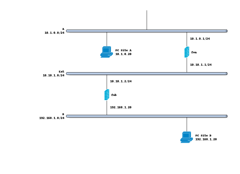
Network topology
The schema below describes the situation we are implementing. Two networks (A,B) and a transit network (10.10.1.0/24) to peer both firewalls.
Preparations
Since our policy based setup doesn’t require interfaces, gateways and routes, we only need to make sure the IPsec module is enabled on the Connections tab and Key pairs are registered for both hosts.
Setting up the IPsec connection
In order to setup a simple (and common) IPsec connection, we go to and add a new entry.
General settings
Side by side the following general settings need to be set in this case, which configures the first part of the security association between both sites:
Property |
site A |
site B |
|---|---|---|
Local addresses |
10.10.1.1 |
10.10.1.2 |
Remote addresses |
10.10.1.2 |
10.10.1.1 |
Press <save> to go to the next step.
Note
One may omit the local address if any address may be used to initiate the connection from, other valid options are also mentioned in the help text of the attribute.
Authentication
Next we will need to add local authentication (add a new record in the local grid):
Property |
site A |
site B |
|---|---|---|
Authentication |
Public Key |
Public Key |
Id |
hostA |
hostB |
Public Keys |
hostA-key |
hostB-key |
Then we need to set Pre-Shared Key for remote authentication as well:
Property |
site A |
site B |
|---|---|---|
Authentication |
Public Key |
Public Key |
Id |
hostB |
hostA |
Public Keys |
hostB-key |
hostA-key |
Note
On host A the private key for Host A should be known and only the public key of Host B, Host B is exactly the opposite.
Children
Finally we may add a child which will add security policies and kernel routes.
Property |
site A |
site B |
|---|---|---|
Mode |
Tunnel |
Tunnel |
Policies |
[checked] |
[checked] |
Local |
192.168.1.0/24 |
10.0.1.0/24 |
Remote |
10.0.1.0/24 |
192.168.1.0/24 |
Save and apply
Finally save the settings and hit apply on the connections page to establish the tunnel.
Install firewall policies
With the tunnel active, all that remains is to accept traffic on this tunnel using the menu option.